help with code 34 and connector confusion...
#1
help with code 34 and connector confusion...
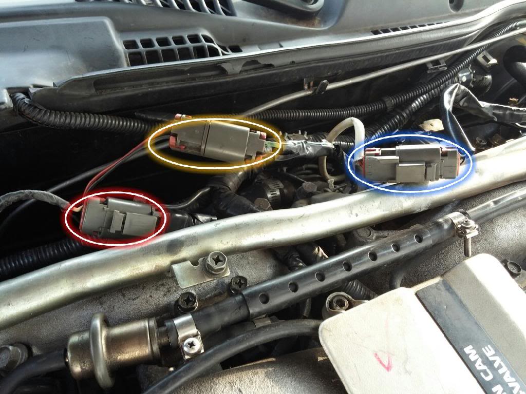
Hey guys, I need a little help with my 1990 z32 NA I just bought. Its giving me the code 34 dtc, so I'm trying to bypass the det sensor to see where the issue lies. After research online I found a page (robo z32 page) that said the vtc connectors and det sensor connector get swapped often by ignorant mechanics. He also stated the det sensor should be connected to a white & grey harness (ecu side) and the vtc should be a black/red & green/black. I found what appeared to be a mistake on mine as the det sensor was attached to a black/red & green/black and the vtc was connected to a white/black on the passenger side. I swapped the vtc and det sensor bypass plug around but it's still a little strange... below is a pic:

-The red circle is where I have the det sensor bypass (resistor) connected to a white & black harness, though it's coming from the passenger side of the engine. It looks like when the PO did a motor swap he messed up where the harness is run because there'd a lot of wiring just dangling.
-The yellow circle is where I plugged in the passenger side vtc into a fairly heavy gauge green/black & red/black wires at the harness.
-The blue circle is where I have the driver side vtc plugged in to a smaller gauge green/black & red/black wires at the harness.
I'm confused at why the green & red harness wires with matching connectors are 2 different gauge wires. Also confused because I am still getting the code 34, which means I'm either bypassing the wrong plug, my resistor didn't work (ohms test good at the pins inside the plug), or the circuit is broken closer to the ecu...
Please help figure out what I'm doing wrong!
#2
please help with code 34 and harness connectors
Hey guys, I need a little help with my 1990 z32 NA I just bought. Its giving me the code 34 dtc, so I'm trying to bypass the det sensor to see where the issue lies. After research online I found a page (robo z32 page) that said the vtc connectors and det sensor connector get swapped often by ignorant mechanics. He also stated the det sensor should be connected to a white & grey harness (ecu side) and the vtc should be a black/red & green/black. I found what appeared to be a mistake on mine as the det sensor was attached to a black/red & green/black and the vtc was connected to a white/black on the passenger side. I swapped the vtc and det sensor bypass plug around but it's still a little strange... below is a pic:

-The red circle is where I have the det sensor bypass (resistor) connected to a white & black harness, though it's coming from the passenger side of the engine. It looks like when the PO did a motor swap he messed up where the harness is run because there'd a lot of wiring just dangling.
-The yellow circle is where I plugged in the passenger side vtc into a fairly heavy gauge green/black & red/black wires at the harness.
-The blue circle is where I have the driver side vtc plugged in to a smaller gauge green/black & red/black wires at the harness.
I'm confused at why the green & red harness wires with matching connectors are 2 different gauge wires. Also confused because I am still getting the code 34, which means I'm either bypassing the wrong plug, my resistor didn't work (ohms test good at the pins inside the plug), or the circuit is broken closer to the ecu...
Please help figure out what I'm doing wrong!

-The red circle is where I have the det sensor bypass (resistor) connected to a white & black harness, though it's coming from the passenger side of the engine. It looks like when the PO did a motor swap he messed up where the harness is run because there'd a lot of wiring just dangling.
-The yellow circle is where I plugged in the passenger side vtc into a fairly heavy gauge green/black & red/black wires at the harness.
-The blue circle is where I have the driver side vtc plugged in to a smaller gauge green/black & red/black wires at the harness.
I'm confused at why the green & red harness wires with matching connectors are 2 different gauge wires. Also confused because I am still getting the code 34, which means I'm either bypassing the wrong plug, my resistor didn't work (ohms test good at the pins inside the plug), or the circuit is broken closer to the ecu...
Please help figure out what I'm doing wrong!
#3
Your FSM has no photos/diagrams to help? If you don't have it, check out http://www.xenonz32.com/reference.html Lotsa other docs, too.
Maybe you can persuade/beg/bribe someone here with a Z32 that runs perfect to take the same photo of their connectors and post them for you here. That would be a cool thing to do... I'd offer $10 and see if there are any takers.
Maybe you can persuade/beg/bribe someone here with a Z32 that runs perfect to take the same photo of their connectors and post them for you here. That would be a cool thing to do... I'd offer $10 and see if there are any takers.

Last edited by zxguy1986; 04-01-2014 at 04:45 PM.
Thread
Thread Starter
Forum
Replies
Last Post
Bookmarks


